The first step in specifying flow measuring instruments is to get opinions and information from the client or end user. It is essential to review the instrumentation, electrical, piping and process standards. Using clients’ standards and preferred manufacturers list is the preferred route. Otherwise, we use our practices and experiences accordingly. We always review our specifications with our client before finalizing them.
Review the piping and instrument diagrams (P&IDs) for the flow instruments and capture relevant information about each to start specifying the flow instruments. Evaluating line lists, process variables, equipment lists, and other notes helps in starting the specification process.
We recommended using specifications sheets because they cover the specifications unique to sensors types and transmitter types. We get what we need and quickly progress through the selection, quoting and procurement. ISA Instrument Specification Sheets are available for these types of flow instruments or our clients have their preferred format for their specifications. Additionally, the specification sheets are valuable records for maintenance, replacement parts and replacements.
The specification sheets have places for the information needed to specify a flow instrument. The list below includes the major headings with many unique fields to each group.
- General
- Process connections
- Process conditions
- Primary element/metering element
- Transmitter
- Counter
You now see what additional information you need to complete a preliminary specification.
Work with process engineers
Work with the process engineers to fill in and complete the process conditions needed. Compatible materials, also known as wetted parts, need to be determined for the process fluids that contact the measuring instruments, not only for temperature and pressure ratings but also for corrosion and erosion properties. Metallurgy needs to be taken into consideration for processes. The state of the fluid is one of the following: gas, liquid, steam, vapor, single or two-phase, slurry or solids. They can be clean or dirty.
Determine whether the measurement is volumetric or mass flow. Determine the measured units of measurement, which depend on the flow technology used. Determine the expected units of measurement. Determine the accuracy required for the flow measurement. Also, use the applicable industry design standards or regulatory requirements, i.e., ASME-BPE, NACE, NFPA, 3A, FDA, cGMP, EHEDG, API, ARC and TUV.
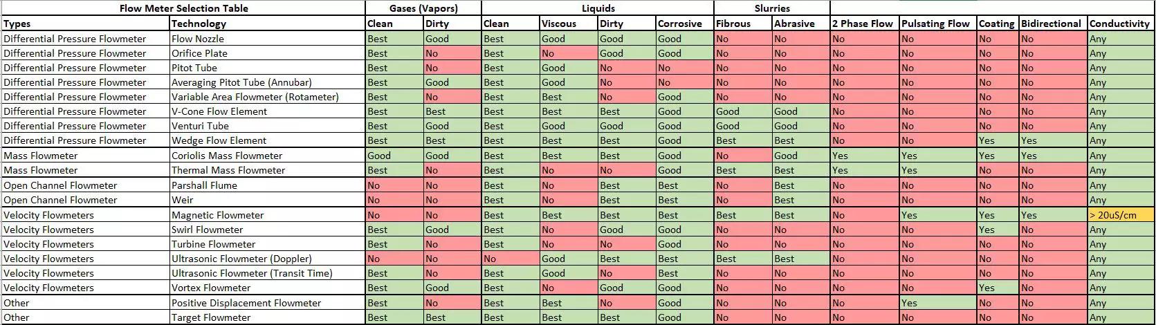
Other process guidelines for selecting instruments include variable area flowmeter (rotameter). Rotameters are not recommended for applications where the process fluid or density is subject to change.
You also need to find out about the installation environment, such as general purpose, hazardous (classified) locations, indoors, outdoors, mining, ambient temperature extremes, corrosives, dust or particulates, wash-down area, food or beverage, and pharmaceutical process areas. The instruments’ enclosures degrees of protection need to be also determined, i.e., NEMA Ratings and IEC 60529 – IPXX.
Coordinate with piping engineers
Coordinate with piping engineers working on the piping layout drawings, isometric drawings, and 3D model for the flow instruments. The flow instruments most often need manufacturer recommended straight pipe runs with lengths upstream and downstream measured in pipe diameters, to obtain straight or laminar flow profiles. Otherwise, the flow profiles are transitional or turbulent, causing flow measurement errors. Install block and tap valves as close as possible to the flow instrument without compromising the upstream and downstream straight pipe lengths. Flow profiles are measured by a value called the Reynolds number (Re). Laminar flow is Re < 2000. Transitional flow is 2000 < Re > 4000. Turbulent flow is Re > 4000.
Liquid flow instruments should be mounted in horizontal lines, provided that they are full all of the time or can be mounted in vertical lines with the pipe full all of the time and with the flow going upward. Mount gas flow instruments in horizontal or vertical lines, free from liquids. The flow instrument needs to be accessible for maintenance, and its display needs to be accessible, or you may want a remote display to read the process variable. Impulse tubing or capillary tubing lengths should be as short as possible and of equal lengths.
Other piping guidelines for installing instruments
Orifice plate (concentric, eccentric, conditioning). For orifice plate installations, install local flow instruments for liquid and steam service below the flow element and above the flow element for gas service.
Coriolis mass flowmeter. Install the meter so that it is in place rigidly without using piping for support. Connect the process piping with no stress, torque or twisting on the inlet and outlet flanges of the meter. When used in liquid service, ensure the flow meter is liquid filled.
Thermal mass flowmeter. When used in liquid service, ensure the flow meter pipe is full.
Electrical wiring requirements for the transmitters and sensors
Determine whether the power will be 120vac or 24vdc or will the 24vdc power and the signal share one pair of wires, also known as a two-wire transmitter? For electronic sensors, the sensor to transmitter wiring is designed by the manufacturer and is described in their specifications. What about the output(s) wiring. Most transmitters’ outputs are a 4 to 20mA signal using two wires, some with 4 to 20mA HART Protocol, and some with 4 to 20mA Honeywell DE Protocol. Some transmitters have relay contacts as an option that are used to signal a transmitter fault, and some can be programmed for a process variable high alarm or a process variable low alarm.
Some transmitters have pulse outputs and frequency outputs; it depends on what attribute you need to measure the process fluid and signal back to a PLC or DCS systems. Transmitters are available with Ethernet IP, Profibus PA, and Foundation Fieldbus. Field wireless is available also and is used for process measurement, diagnostics, control and asset management applications, where long wiring lengths may be prohibitive. Wireless protocols used are IEC62591-1 WirelessHART or ANSI/ISA100.11a–2011. Some transmitters have self-diagnostics also. For safety instrumented systems, transmitters are available having the safety integrity level (SIL) ratings.
Other electrical guidelines for installing instruments include:
Magnetic flowmeter. Ensure that magnetic flow meters are grounded according to the manufacturer’s requirements. This requirement is especially important when using non-ferrous pipeline materials.
Ultrasonic flowmeter (Doppler) and (transit time). Ensure transponders are installed with liberal amounts of manufacturer’s recommended ultrasonic conduction compound. Ensure transponders are installed in the same plane with each other.
Discuss with the PLC, DCS and HMI programmers
Programmable logic controller (PLC) or distributed control system (DCS) programming requirements generally are flow rate accuracy and flow totalizing accuracy defined by the process, whether it be an indication only of the process variable, process control, clean-in-place, pasteurizing, or batching. Flow totalizing transmitters have pulsed outputs that are inputted to a high-speed counter card. Flow rate transmitters have an analog output signal of 4 to 20mA calibrated to a specific flow rate range in engineering units, are input to an analog input card. Coriolis mass flow meters also have an optional analog output for density measurement. Many flow transmitters use Ethernet IP output instead of analog outputs.
Other helpful information
Custody transfer is the measurement to determine the costing of material transfer between suppliers and consumers, requiring high accuracy and reproducibility as small errors can have significant cost consequences.
When in doubt, call the manufacturer or their representative and ask questions about their instruments. They know their instruments the best, most of the time. Request instruments cut sheets, because they are valuable references for installation as far as piping and electrical connections are concerned and process’ design verification and evaluation of instruments selection. Keep this documentation.
Correct calibration and maintenance are essential for measuring flow. Our clients’ operations, instrument technicians and engineering teams most probably have a schedule for which to check the calibration and operation of their flow instruments and recalibrate them at a set periodic cycle. The instruments should be bench tested and calibrated in the instrument shop, even though they may have been factory calibrated.
Important terminology that you will encounter
- The value that the flow meter measures compared to the known value.
- Percent of rate accuracy – This states that throughout a given range, the uncertainty of flow in +/- gallons per minute is proportional to flow rate. As flow decreases, the amount of error decreases. This usually applies to meters that determine the flow rate by measuring fluid velocity.
- Percent of full-scale accuracy – This value states that throughout a given range, the uncertainty of flow in +/- gallons per minute remains constant. Error as a percentage of the reading increases as flow reading decreases.
- An instrument’s accuracy depends on the measuring technology used, plus the design, installation and maintenance of the instrument.
Turndown or Rangeability
- Turndown is the ratio of maximum flow to minimum flow, but not zero flow; flow rates under which a flowmeter can maintain measurement accuracy.
Repeatability
- The ability of a flowmeter to produce the same measurement each time it measures a flow.
- Sometimes, repeatability is more important than accuracy.
- Repeatability is the characteristic of a flow meter to indicate the same readings every time the same flow conditions exist.
- Repeatability of an instrument is a feature of the measurement technology used. Repeatability is defined for a constant flow.
Accuracy vs. repeatability
- Poor repeatability means poor accuracy.
- Good accuracy means good repeatability.
- Good repeatability does not always mean good accuracy.
It is good to have a path to follow in this work flow process, so that you have sources of information to guide you, templates to use, and colleagues in the related engineering disciplines to communicate with to come to an engineering solution.
Matrix Technologies is one of the largest independent process design, industrial automation engineering, and manufacturing operations management companies in North America. To learn more about our multidiscipline engineering capabilities and manufacturing process control solutions, contact Bob Kurczewski.
© Matrix Technologies, Inc.